Your project failed, and you don't know why. The lights are failing, the effect is flat, and the client is unhappy. You need to avoid these costly mistakes.
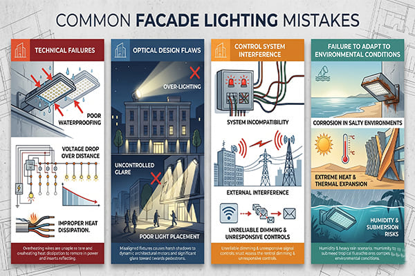
The most fatal mistakes in facade lighting projects fall into four categories. These are technical failures like poor waterproofing and voltage drop1, optical design flaws like over-lighting, control system interference, and a failure to adapt to the environmental conditions like heat and water.
I've been in the outdoor lighting business for over a decade. I've seen magnificent successes and heartbreaking failures. The failures almost always trace back to a few common, avoidable mistakes. Getting these fundamentals right is the difference between a landmark project and a maintenance nightmare. I want to walk you through the biggest pitfalls I see, so you can learn from others' mistakes and ensure your project shines for years to come. Let's dive into the details.
Are Technical Oversights the Biggest Threat to Your Project's Lifespan?
Fixtures are failing years ahead of schedule. Your team is constantly on-site for repairs, and costs are spiraling. This happens when critical technical details are overlooked during installation.
Yes, technical mistakes are a primary cause of premature project failure2. The top offenders are waterproofing failures due to the capillary effect3, severe voltage drop dimming lights, and placing power supplies in inaccessible locations, which turns minor maintenance into a major overhaul.

In my experience as an outdoor lighting specialist, the technical side is where projects often fall apart silently. A beautiful design means nothing if the lights don't last. I’ve been called to fix too many projects where simple technical errors led to catastrophic failures. These aren't complex issues. They are basic principles that get ignored in the rush to finish a job. Let's break down the three most lethal technical mistakes I see time and time again.
The Capillary Effect: The Silent Killer
Many contractors think a high IP rating is enough for waterproofing. They are wrong.4 The biggest threat I see is something called the "capillary effect." When there's a temperature difference between the outside and inside of a light fixture, a pressure difference is created. This pressure can suck water vapor through the tiniest gaps along the copper strands of a power cable, completely bypassing the IP-rated seals. The moisture condenses inside the fixture, shorting out electronics. The only way to stop this is to create a perfect seal at the cable joint. You must use high-quality waterproof junction boxes and, for maximum protection, inject them with potting glue or use gel-filled connectors. This creates an impassable barrier and is non-negotiable for long-term reliability.
Solving the Voltage Drop Puzzle
Have you ever seen a long line of linear lights where the ones at the end are noticeably dimmer or have a different color? That’s voltage drop. In low-voltage DC systems, the electrical resistance of the cable itself consumes energy over distance. The longer the cable and the thinner the wire, the more voltage is lost.5 By the time the power reaches the last fixture, it's not enough to run it at full brightness or correct color temperature. The solution is proper planning. You must calculate the total load and distance to select the correct wire gauge.
| Cable Run Length | Recommended Wire Gauge (AWG) for 24V System | Result |
|---|---|---|
| 0 - 15 meters | 16 AWG | Minimal voltage drop, consistent brightness. |
| 15 - 30 meters | 14 AWG | Prevents noticeable dimming at the end. |
| Over 30 meters | 12 AWG or Thicker | Ensures power integrity for long runs. |
Note: This is a simplified guide. Always perform precise calculations for your specific project's load.
Accessible Power Supplies Are Non-Negotiable
This seems obvious, but I see this mistake constantly. In an effort to hide equipment, LED drivers and power supplies are buried inside walls or sealed in ceiling cavities with no access panels. It looks clean on day one. But a year later, when a single driver fails, the maintenance team has to cut open walls or dismantle parts of the facade to replace a simple component. A one-hour job becomes a two-day deconstruction project. The rule is simple: Every single power supply must be installed in a location that allows for easy inspection, repair, or replacement. Plan for maintenance from day one. It will save you enormous headaches and expense down the road.
Is Your Lighting Design Making the Building Look Worse?
You spent a fortune on high-end lights. But at night, the building looks flat, harsh, or has weird dark spots. The architectural details you wanted to highlight have vanished.
It might be. A common design sin is over-lighting, based on the false idea that "brighter is better." Other mistakes include ignoring how light interacts with different building materials and choosing the wrong beam angles, which completely ruins uniformity and visual comfort.
Great facade lighting is not about flooding a building with light. It’s an art form. It's about using light and shadow to reveal the building's soul at night. The goal is to enhance the architecture, not erase it. I've consulted on projects where the client's initial request was just to "make it bright." This is a recipe for disaster. A truly successful design is a sophisticated balance of intensity, color, and focus. It requires a deep understanding of optical principles and how they interact with the physical structure. Let’s look at the most common ways lighting design goes wrong.
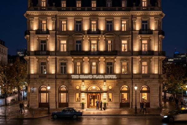
The "Brighter is Better" Myth
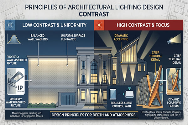
The single biggest misconception in facade lighting is that more light equals a more premium look. The opposite is true.6 Blasting a building with uniform, high-intensity light flattens its features, eliminates depth, and creates a cheap, glaring effect.7 True sophistication comes from contrast. You must create a visual hierarchy. The most important architectural elements, like the main entrance or a bell tower, should receive the most light. Secondary surfaces should be lit more softly, and some areas might be left in shadow intentionally. This contrast guides the eye, creates a sense of three-dimensionality, and produces a far more elegant and powerful result.
| Architectural Element | Relative Brightness Level | Desired Effect |
|---|---|---|
| Main Entrance / Focal Point | 100% | Draws attention, feels welcoming. |
| Primary Facade | 60-70% | Defines the main building form. |
| Secondary Wings / Walls | 30-40% | Provides context and depth. |
| Decorative Details | 80-90% (Grazing) | Highlights texture and craftsmanship. |
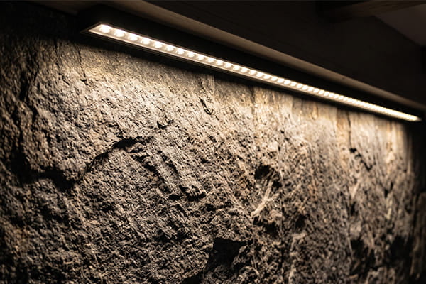
Respect the Building's Materials
Different materials react to light in completely different ways.8 You cannot use the same lighting technique on a glass curtain wall as you would on a rough stone facade. For example, trying to floodlight a modern glass building head-on is a terrible idea9. It will create massive amounts of glare and reflections, hiding the building behind a sheet of light. For glass, it's far better to use contour lighting to outline the shape or to light the interior so the building glows from within. Conversely, rough materials like brick or textured concrete are perfect for light grazing—placing lights close to the surface at a sharp angle. This technique casts tiny shadows that dramatically reveal the material's texture and depth. Always test your lighting on a material sample first.
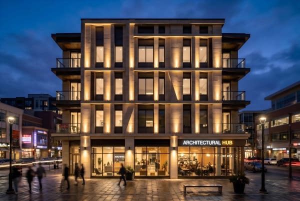
Beam Angle is Everything
The beam angle of a fixture determines how wide or narrow the cone of light is.10 Choosing the wrong one is a guaranteed way to ruin a design. A beam angle that is too wide will cause light to spill between fixtures, creating a messy, overlapping effect and wasting energy. A beam that is too narrow will create harsh "hot spots" on the facade with distracting dark areas in between. Achieving a smooth, uniform wash of light requires calculation. You have to consider the fixture's distance from the wall (setback), the spacing between each fixture, and the height you need to cover. Only by balancing these three variables can you select the perfect beam angle to achieve the seamless effect you envision. There is no guesswork here; it must be planned.
Are Control Systems and the Environment Undermining Your Design?
The whole building's lighting system is flickering randomly. Fixtures are failing in recessed slots. You're getting complaints about light pollution from neighbors. These are signs of system and environmental conflicts.
Yes, they absolutely can. Running signal cables next to power lines causes electrical interference that makes lights flicker. Ignoring heat and water drainage in installations cooks LEDs to an early death. And using high-power floodlights without shields creates light pollution that angers the community.
A lighting project isn't finished when the last fixture is mounted. The system has to work reliably within its environment. I’ve seen perfectly installed fixtures fail because their control signals were corrupted. I’ve also seen top-of-the-line LEDs lose half their brightness in a year because they were installed in a way that trapped heat and water. Finally, a project can be a technical success but a social failure if it negatively impacts the surrounding area. A truly professional approach considers the entire ecosystem of the project, from the electrical signals to the flow of rainwater and the view from a neighbor's window.
Keeping Signals Clean
In dynamic lighting systems, control signals (like DMX or SPI)11 tell the lights what to do. These are low-voltage data signals and are highly susceptible to electromagnetic interference (EMI)12. The most common cause of EMI is running signal cables in the same conduit or right alongside high-voltage power lines. The powerful magnetic field from the power cables induces "noise" in the signal cables, corrupting the data. This results in flickering, stuttering colors, or a total loss of control. The solution is simple but crucial: physical separation. Keep signal and power cables in separate conduits or at least a foot apart. For long-distance signal runs, typically over 100 meters, you must also install a signal amplifier (or booster) to regenerate the data and ensure it arrives at the last fixture with full strength.
The Dual Threat of Heat and Water
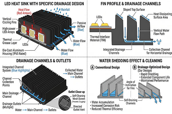
LEDs are sensitive to heat. Excessive heat dramatically shortens their lifespan and accelerates lumen decay, meaning they get dimmer faster. When fixtures are installed in recessed channels or tight coves, this becomes a critical issue. If there is no path for air to circulate, heat builds up and literally bakes the fixture. The same channel can also trap rainwater or condensation. This standing water, combined with the heat, creates a corrosive, humid microclimate that is deadly for electronics. Therefore, any recessed installation must be designed with both ventilation and drainage in mind. This means including weep holes for water to escape and ensuring there is enough space for convective airflow to carry heat away. This is as much an architectural design detail as it is a lighting one.
Being a Good Neighbor: Avoiding Light Pollution
Your project does not exist in a vacuum. Uncontrolled light can be a major nuisance. Light trespass (spilling into neighboring windows) and sky glow (useless light directed upwards) are serious issues that can lead to public complaints and even municipal fines. This is especially true with powerful floodlights. A responsible design puts light only where it is needed: on the building facade. This is achieved through both careful fixture selection and the use of accessories. Always choose fixtures with precise optics that match the target area. In addition, use accessories like shields, louvers, or snoots to cut off any stray light and prevent it from spilling into the sky or onto adjacent properties. Great lighting enhances the community, it doesn't annoy it.
Conclusion
Ultimately, successful facade lighting is not about installing many lights. It's about precise control, enhancing architecture, creating depth, and working smarter, not harder, right from the very beginning.
"Voltage Drop", https://courses.ems.psu.edu/ae868/book/export/html/967. Electrical-engineering references explain that conductors have resistance and that voltage drop increases with current, cable length, and conductor resistance, supporting the article’s explanation of dimming in long low-voltage runs; the source would not validate the article’s specific gauge table unless it includes matching load assumptions. Evidence role: mechanism; source type: education. Supports: Voltage drop in cable runs can reduce voltage available to fixtures, especially in long low-voltage circuits.. Scope note: Supports the electrical principle, not the simplified gauge recommendations unless load-specific calculations are provided. ↩
"Lighting in buildings - Top Tips - CIBSE", https://www.cibse.org/knowledge-research/knowledge-portal/lighting-in-buildings-top-tips?id=a0q20000006oaz1AAA. A building-services or lighting maintenance source can support that installation and system-design deficiencies are common contributors to premature lighting-system failures; this evidence is contextual because failure rates vary by product quality, climate, and maintenance regime. Evidence role: general_support; source type: institution. Supports: Technical mistakes are a primary cause of premature facade lighting project failure.. Scope note: Contextual support rather than direct proof for all facade lighting projects. ↩
"Capillary pressure - Wikipedia", https://en.wikipedia.org/wiki/Capillary_pressure. A physics or engineering source can define capillary action as the movement of liquid through narrow spaces due to surface-tension effects, supporting the mechanism by which moisture may migrate through small gaps or cable interfaces; it does not by itself quantify the risk in a specific luminaire assembly. Evidence role: definition; source type: encyclopedia. Supports: Capillary action can draw moisture through small spaces and is relevant to waterproofing risks.. Scope note: Defines the physical mechanism but does not directly prove failure frequency in facade fixtures. ↩
"IP code - Wikipedia", https://en.wikipedia.org/wiki/IP_code. IEC-based ingress-protection references describe IP ratings as standardized tests for enclosure protection against solids and water, supporting the point that an IP code addresses defined test conditions rather than every installation-related moisture pathway; this is contextual because the exact limitation depends on the fixture and installation method. Evidence role: definition; source type: institution. Supports: An IP rating alone does not guarantee waterproof performance under all real installation conditions.. Scope note: Supports the scope of IP ratings generally, not a specific product failure mode. ↩
"[PDF] Electrical Tech Note — 227 - Michigan State University", https://www.maec.msu.edu/application/files/1017/1923/9646/Tech_Note_227_Voltage_Drop.pdf. An electrical-engineering source can document that voltage drop is proportional to current and conductor resistance, and that resistance rises with longer length and smaller cross-sectional area; this directly supports the article’s general statement but not any particular installation limit. Evidence role: mechanism; source type: education. Supports: Longer and thinner conductors produce greater voltage drop.. Scope note: Does not establish acceptable voltage-drop thresholds for a specific facade lighting project. ↩
"[PDF] Introduction to Interior Lighting Design - OHIO Personal Websites", https://people.ohio.edu/ziff/ARTI%20288/Intro%20to%20Interior%20Lighting%20Design.pdf. Lighting-design guidance from professional or academic sources can support that visual quality depends on luminance distribution, contrast, glare control, and hierarchy rather than maximum illuminance alone; this is partly normative because aesthetic judgments vary by context and design intent. Evidence role: expert_consensus; source type: institution. Supports: Facade lighting quality is not determined simply by increasing brightness.. Scope note: Supports professional design principles, not a universal aesthetic rule for every building. ↩
"[PDF] Computer modeling of LED light pipe systems for uniform display ...", https://www.lrc.rpi.edu/s/SPIE4445-22_VanDerlofske.pdf. Architectural-lighting literature can support that shadows, contrast, and controlled luminance patterns are used to reveal form and depth, while excessive uniform illumination can reduce modeling and increase glare; the characterization of the effect as “cheap” remains an aesthetic judgment. Evidence role: expert_consensus; source type: education. Supports: Excessive uniform lighting can reduce perceived depth and increase glare.. Scope note: Supports the optical/design principle, not the subjective value judgment in the wording. ↩
"Lighting Design: Materials - Research Guides - The New School", https://guides.library.newschool.edu/lightingdesign/materials. Architectural-lighting and materials references describe how surface reflectance, texture, gloss, and transparency affect reflected light, supporting the claim that facade materials require different lighting approaches; this evidence is general rather than a prescription for a specific facade. Evidence role: mechanism; source type: education. Supports: Building materials interact with light differently because of reflectance, texture, gloss, and transparency.. Scope note: General material-light interaction support, not a project-specific design calculation. ↩
"Facade lighting: displaying buildings - ERCO", https://www.erco.com/en_us/designing-with-light/public/correctly-illuminating-facades-7226/. Sources on glass optics and architectural lighting can support that glass has specular reflection and transmission properties that can produce glare and reflections under direct illumination; the judgment that the technique is “terrible” depends on design goals and site conditions. Evidence role: mechanism; source type: education. Supports: Direct floodlighting of glass facades can produce glare and reflections because of glass’s optical properties.. Scope note: Supports the optical risk, not an absolute prohibition on head-on lighting of glass facades. ↩
"Light Fixture Beam Angles – What are they and Why Should I Care?", https://www.ledlightexpert.com/light-fixture-beam-angle?srsltid=AfmBOooIzA6VIz98IeMvOKjAXd5vwXwwEfiPOyUHEnwUUV4qG1hCHgKY. Lighting-engineering references define beam angle as the angular spread of a luminaire’s light output, commonly related to the intensity distribution of the beam, supporting the article’s description of beam width; exact definitions may vary by standard or manufacturer photometric convention. Evidence role: definition; source type: institution. Supports: Beam angle describes the angular width of a luminaire’s light output.. Scope note: Definition-level support; does not determine the correct beam angle for a specific design. ↩
"DMX512 - Wikipedia", https://en.wikipedia.org/wiki/DMX512. Technical references on DMX512 and serial lighting-control protocols can establish that DMX is a digital control standard used for stage and architectural lighting, supporting the article’s identification of control signals in dynamic lighting systems; SPI use is more product-specific and may need a separate source. Evidence role: definition; source type: institution. Supports: Dynamic lighting systems use low-voltage control/data signals such as DMX, and sometimes SPI-based control, to command fixtures.. Scope note: Directly supports DMX as a lighting-control signal; SPI support may be contextual depending on fixture architecture. ↩
"How To Protect Low Voltage Wiring: Complete Guide", https://clrnet.net/how-to-protect-low-voltage-wiring-complete-guide/. Electromagnetic-compatibility references can support that low-voltage signal circuits may be disturbed by electromagnetic coupling from nearby power conductors, especially without adequate separation, shielding, or grounding; the severity depends on cable type, current, installation geometry, and equipment immunity. Evidence role: mechanism; source type: government. Supports: Low-voltage lighting control cables can be affected by electromagnetic interference from nearby power wiring.. Scope note: Supports the EMI mechanism generally, not the exact separation distance stated in the article. ↩